Understanding AP power levels
Published by joe on 07/08/2018 07/08/2018.
WLAN power levels are easy, right? In Europe you “know”, that the maximum WLAN transmit power is 100 mW (20 dBm). However, this is true for the 2,4 GHz band and the limit describes the EIRP ( equivalent isotropically radiated power ).
This means, if there is a regulatory limit of 100 mW (20 dBm), the maximum power you are allowed to configure on the AP, depends on the antenna you are using, because the antenna gain must be included in the calculation as well:
TX (AP_max) = RegulatoryLimit – AntennaGain
For example: If an antenna with 3 dBi is used, the max. TX power on the AP side (for the 2,4 GHz band) is 17 dBm (TX (AP_max) = 20 dBm – 3dB).
Easy, right?
However, it becomes more complicated for the 5 GHz band, because it depends on the band (channel) you are using and on the 802.11h (DFC and TPC) capabilities. I illustrated the regulatory limit for Europe / ETSI in the following figure:
Today, the WLAN equipment is typically DFS and TPC capable, to use may use the channels 36 – 140 in Europe. The channels 120, 124 and 128 are grayed out, because Cisco left them out, because there is critical radar (aviation, weather) equipment on these channels.
A little bit more complex, but still easy, right?
However (sigh), this is still not the complete picture. The regulatory limits must be met, if multiple TX antennas send at the same time (MIMO).
This means in theory (caution: result is in mW – input in dB)
Using the same example from above, the result is 33mW (~15dBm) for three TX antennas and 25mW (~14dBm) using four antennas.
So in fact, for SISO client the max TX power per stream is higher compared to a MIMO client using multiple streams and beamforming.
Caution: If a client is using three streams and additionally ClientLink (beamforming) is used, four transmit antennas are used in total!
Easy, somehow … whatever 🙂
So what is the take home message until now? The TX power per antenna is different and depends on:
- Number of TX antennas (spatial streams, beamforming)
- Regulatory limit
- Antenna gain
However, the Cisco WLC and the APs only displays ONE TX power value per power level, as illustrated in the output below (example for an 2802i AP):
On channel 100, the max TX power (power level 1) is 23 dBm if four antennas are active. The AP offers a more detailed output:
The total power (allowed total powers) matches the WLC output (23 dBm). However, the TX power per antenna is 17 dBm. This means:
If a frame is sent to a MIMO client with three spatial streams and beamforming, the total TX power is 23 dBm (17 dBm * 4). The EIRP per antenna is ~22 dBm (158mW). The total EIRP for all antennas is ~28 dBm (631mW).
If a frame is sent to a SISO (legacy 802.11a) client with one stream, the total TX power is 17 dBm (17 dBm * 1). The EIRP per antenna (and total) is ~21 dBm (125mW).
Here’s a summary how the outputs of the AP, the WLC and the “channels and maximum power level” sheet from Cisco correlate (2802i example):
Note: The power level, which defines the cell size is the power level for the single stream . Beacon frames are sent at the lowest mandatory/basic data rate, which is typically a legacy 802.11a/b/g data rate. These frames are always transmitted using ONE antenna.

Leave a Reply Cancel reply
Related posts, uncategorized, wesp9: wireless endpoint statistics ping.
My weekend work was to create a successor or the wesp(1) tool. So the original wesp was designed to communicate with an AireOS WLC to get “ping alike” statistics for a single wireless client (via Read more…

EAP TLS ciphers
In many projects regarding network access control are focussing on probably secure EAP methods, which rely on SSL/TLS. The most common examples are EAP-TLS or PEAP (simply because must supplicants support them). However, it’s not Read more…
DHCP / DHCPv6 tests using Docker
Hi, today a colleague and myself wanted to test first hop security features in an ACI fabric. To be more precise DHCP policies (a.k.a DHCP snooping) for IPv4 (DHCP) and IPv6 (DHCPv6). Normally we’re testing Read more…
Privacy Overview

WLC and AP Power settings
Ap power settings made easy.
To fully understand and sometimes troubleshoot our wireless networks, we need to know exactly what is going on with our AP s, especially what power they are outputting. So in this post we are going to look at AP Power settings made easy.

Cyber Security: An Uphill Battle?

AI - Why All the Hype?

Have questions? Ready to find to get started?
Important Notice: NC-Expert does not accept enrollment applications from independent individuals. We require that employers pay for their employees. We continue to service corporate clients, using B2B transactions, with no change in service. We apologize for any inconvenience.

Our vision is to provide innovative, relevant, and accessible technical consulting and training for executives and engineers which will enable them to directly impact the growth of their companies.
Get In Touch
+1 (855) 941-2121
5113 Johnson Dr
Pleasanton, CA 94588
Enrollment T&Cs
NC-Expert - All Rights Reserved
Privacy Policy | Enrollment T&Cs
Wait, but Wi-Fi?
Transmit Power Control Considerations
Proper configuration of Transmit Power Control (TPC) settings can help to ensure that your Access Point (AP) does not speak too loudly. If your AP is transmitting at 18dBm and an associated client station (STA) is at the cell edge and only capable of transmitting at 15dBm, your client will be able to hear the AP transmission, but the AP won’t be able to hear the client which leads to retransmissions and thus reduced performance.
Wireless network design is ultimately dependent upon the clients it is to support, so we will want to have an idea of what our intended clients are capable of. As an example, one of my customer’s clients is an HP EliteBook 8470p laptop workstation which has a Broadcom BCM943228HM4L Wi-Fi adapter. According to the product specification web page for this particular model, I was able to find that it is capable of transmitting at around 15dBm. If this is my customer’s least capable device, I would not want my AP to transmit louder than 15dBm either.
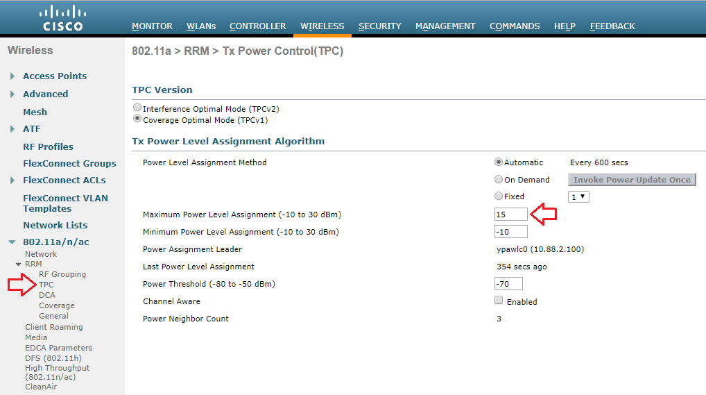
My customer is using a Cisco 3504 Wireless Controller running AireOS version 8.8. I am able to globally configure the Maximum Power Level Assignment to 15dBm.
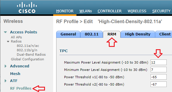
If the same controller were managing multiple locations with different requirements, I can also set a Maximum Power Level Assignment for different RF Profiles.
Though the maximum power level is configured in dBm, Cisco uses a series of numbers to represent levels of power. Phil Morgan of NC-Expert wrote an article titled WLC and AP Power settings in which he discusses Cisco power levels in further detail. In his article, he discusses how we can determine what the power levels represent as they vary by AP model, band (2.4 vs 5GHz), and even channel groupings (i.e. U-NII 1, 2, 2e, 3).
I also stumbled upon an excellent post by Maxim Risman in the Cisco Community titled Cisco Access point 2802i Tx Power Chart where he demonstrates the use of another very helpful command which summarizes the power levels of all APs: show advanced 802.11a txpower
Note that the range for the power levels actually does not change, but rather TPC is limiting the highest level that can be used.
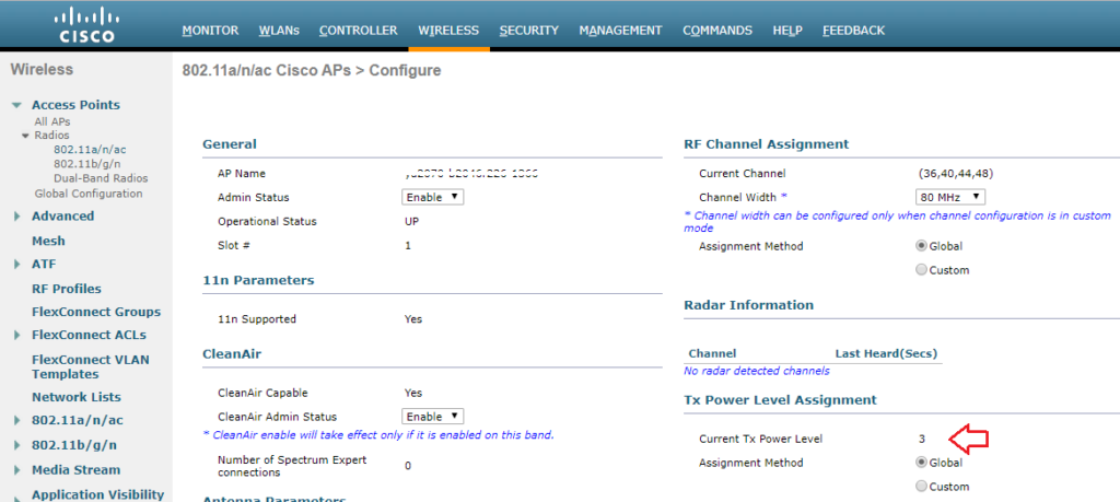
The current power level setting can also be found in the web GUI by navigating to Wireless > Access Points > Radios. There, you can see the power level for all of your APs in a column, or you can dive in to the configuration of a radio.
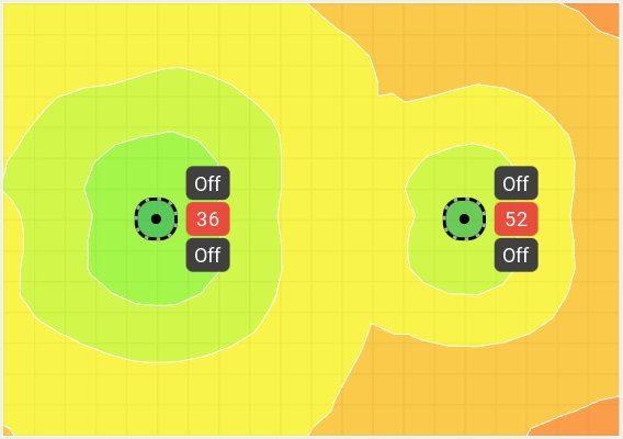
When performing predictive site surveys with Ekahau Pro site survey software, we have the ability to adjust the transmit power with which to generate our expected heat maps.
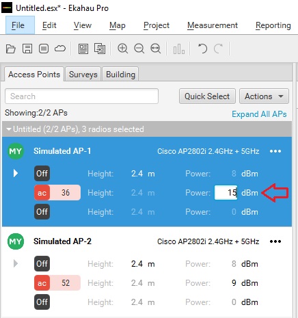
We can get an idea of how this difference may affect our design in the real world.
If you are interested in getting deeper into Cisco’s TPC implementation, you may want to check out a whitepaper they have published titled Transmit Power Control (TPC) Algorithm .

Published by Stephen
View all posts by Stephen
Welcome to the world of wireless networks !!!
Cisco access point transmit power levels
In this blog, I would like to explain how we could interpret transmit power levels on the Cisco controllers and access points.
On 2.4 Ghz, the transmit power levels is not that complicated.it is pretty much dependent on the allowed transmit power and antenna gain. The max power level shows 23 dBm with power levels ranging from 1 to 8, where Power level 1 is 23 dBm.

Below is the categorisation of 5 GHz frequency:
UNII-1 channels =36,40,44 & 48 UNII-2 channels = 52,56,60 & 64 UNII-2e channels =100,104,108,112,116,120,124,128,132,136 & 140 UNII-3 channels =144,149, 153, 157 , 161, 165
These power levels are dependent on various factors like AP Type, assigned channels, regulatory domain, antenna gain etc.
Depending on the UNII band/frequency of the AP, the power levels are different on the 802.11a 5GHz radio.
On Cisco WLC, transmit power level is a numeric value instead of an unit in mW or dBm.
The numeric value corresponds to a power level that varies depending on the regulatory domain, frequency used and antenna gain.
Power level 1 is always the maximum power level allowed for that particular access point, deployed in a particular country and operating on a particular channel.
We can safely consider that each successive power level represents 50% of the previous power level. For example, 1 = maximum power level in a particular regulatory domain, 2 = 50% power, 3 = 25% power, 4 = 12.5% power, 5=6.25% etc.
If you set the maximum power level assignment under RF profile, the max transmit power level under the WLC will not be this max value but it takes the max value of the radio in that regulatory domain along with its antenna gain.
For some reason, quite often, I have also noticed that transmit power levels are reduced by 1 dB than the actual allowed values: Eg: if max allowed power is 23 dB, have seen it as 22 dB on the WLC and AP.
Below are the commands that can be used on plc or AP to see the transmit power levels:
for 5 GHz ” show ap config 802.11a (AP name)”
For 2.4 GHz “show ap config 802.11b (AP name)
On the Access point:
show controller dot11radio 1
show controller dot11radio 0
Based on the output you can see that different access points operating on different channels show different power levels.
The best way to validate transmit power is by using above 2 commands.
Please note that the antenna gain has to be configured manually on the wireless lan controller

Share this:
Leave a comment cancel reply.
Not Another Wireless Blog
My CCIE Wireless Journey & More.....

- Already have a WordPress.com account? Log in now.
- Subscribe Subscribed
- Copy shortlink
- Report this content
- View post in Reader
- Manage subscriptions
- Collapse this bar
WLAN Lessons Learned
Power levels, channels and maximum power settings for cisco 3700.
The Tx Power Level Assignment for each AP shows its current power level assignment in a numbering system that starts with 1 and ends with 8. The number 1 indicates the AP is on full power and the higher the number goes less power are transmitted.
That number (1-8) can be converted to dBm or mW to show the AP’s actual power output by using this command ‘show ap config 802.11a’. It is here where you might notice the power level of APs all on power level 1 might not be transmitting the same dBm or mW.
The reason for this is the UNII band the AP is on for example below is an extraction of the ‘show ap config 802.11a’ command for three APs. All three AP’s were configured exactly the same except for Dynamic Channel Assignment (DCA) which put them on three different UNII bands.
Tx Power Num Of Supported Power Levels …………. 3 Tx Power Level 1 …………………….. 8 dBm Tx Power Level 2 …………………….. 5 dBm Tx Power Level 3 …………………….. 2 dBm Tx Power Configuration ……………….. AUTOMATIC Current Tx Power Level ……………….. 1 Tx Power Assigned By …………………. DTPC Phy OFDM parameters Configuration ……………………….. AUTOMATIC Current Channel ……………………… 36 Channel Assigned By ………………….. DCA
Tx Power Num Of Supported Power Levels …………. 5 Tx Power Level 1 …………………….. 16 dBm Tx Power Level 2 …………………….. 13 dBm Tx Power Level 3 …………………….. 10 dBm Tx Power Level 4 …………………….. 7 dBm Tx Power Level 5 …………………….. 4 dBm Tx Power Configuration ……………….. AUTOMATIC Current Tx Power Level ……………….. 1 Tx Power Assigned By …………………. DTPC Phy OFDM parameters Configuration ……………………….. AUTOMATIC Current Channel ……………………… 100 Channel Assigned By ………………….. DCA
Tx Power Num Of Supported Power Levels …………. 8 Tx Power Level 1 …………………….. 23 dBm Tx Power Level 2 …………………….. 20 dBm Tx Power Level 3 …………………….. 17 dBm Tx Power Level 4 …………………….. 14 dBm Tx Power Level 5 …………………….. 11 dBm Tx Power Level 6 …………………….. 8 dBm Tx Power Level 7 …………………….. 5 dBm Tx Power Level 8 …………………….. 2 dBm Tx Power Configuration ……………….. AUTOMATIC Current Tx Power Level ……………….. 1 Tx Power Assigned By …………………. DTPC Phy OFDM parameters Configuration ……………………….. AUTOMATIC Current Channel ……………………… 149 Channel Assigned By ………………….. DCA
All three APs indicate Power Level 1 on the Wireless LAN Controller but their actual power transmit power is: AP1 = 8dBm AP2 = 16dBm AP3 = 23dBm
With this information available you might want to disable certain UNII-bands as the power output is not enough for the environment the APs are in.
Below is the path to get to the Cisco provided spreadsheet indicating what the power setting will be for your regulatory domain using certain antennas, configuration settings and certain UNII-bands.
http://www.cisco.com/c/en/us/support/wireless/aironet-3700i-access-point/model.html
Under Install and Upgrade Guides click on Detailed Channels and Maximum Power Settings for Cisco 3702e and 3702i Series Access Points.
Have fun.
Share this:
- Click to share on LinkedIn (Opens in new window)
- Click to share on Facebook (Opens in new window)
- Click to share on Twitter (Opens in new window)
- Click to share on Tumblr (Opens in new window)
- Click to print (Opens in new window)
- Click to email a link to a friend (Opens in new window)
NDP packets on Cisco 3700 abnormally low
This post is a follow up from last weeks one-way audio issue. Although we did resolve the one-way audio by disabling A-MSDU we also found a bug on the Wireless LAN Controller that caused Neighbour Discovery Protocol (NDP) packets to be abnormally low and thus causing the TX power of the Access Point (AP) to be excessively high (power level set to 1) and channel assignment not working at all. I’ve noticed this bug twice in the last month at different customers.
This bug only affected the 5GHz radios as seen in the diagrams below and not 2.4GHz. Diagram 1 shows power levels for 5GHz on the right and Diagram 2 shows power levels for 2.4GHz on the right for the same AP’s.

I monitored ten AP’s in a particular area. Seven of these AP’s would stay on power level 1 and would not change while the other three AP’s in this area would change its power level on the 10 minute mark (as per default) and change between power levels 2-5 on a continuous basis. On the second occasion I saw this the client had about 25 AP’s on site and all of them was stuck on channel 36 and power level 1.
This could be the root cause of one-way audio. It is important to understand that wireless communication occurs in a bi-directional manner. Uplink communication from the client to the AP is not always the same as downlink communication from the AP to the client. While an AP will send beacons downlink to the VoWLAN handset, most surveying tools will only display information as it pertains to downlink transmissions; therefore some problems are not easily detected using pre- or post-site survey tools. While a post site survey is vital after deploying the WLAN, a survey tool may not take into consideration the uplink signal being transmitted by the wireless IP phone in comparison to the downlink signal.
Most access points will often have a higher transmit power + the antenna gain than the VoWLAN handset. When this occurs, the IP phone will still hear the downlink frames sourced from the AP, but the AP will not hear the uplink frames from the wireless IP phone and this leads to possible one-way audio.
The workaround prescribed by Cisco would be to manually assign channel/power settings which could turn into a timeous process or as the update of this bug shows from 6 November 2014 you can upgrade to the releases mentioned below.
The equipment used in this case are:
- Cisco 5508 Wireless LAN Controller
- Cisco 3700 series Access Point
The software affected by this bug (CSCuq86750) are:
The known fixed releases are:
- 7.6(130.10)
- 7.6(130.204)
Reference http://www.cisco.com/c/en/us/td/docs/wireless/technology/vowlan/troubleshooting/vowlan_troubleshoot/2_Gen_Troubleshooting_Guidelines.html#wp1054631 https://tools.cisco.com/bugsearch/bug/CSCuq86750
- Already have a WordPress.com account? Log in now.
- Subscribe Subscribed
- Report this content
- View site in Reader
- Manage subscriptions
- Collapse this bar
Get the Reddit app
Wireless ap power levels and global assignments question.
Trying to figure out some wireless issues in a school environment, have multiple Cisco AP's (mainly 9120's) throughout the school campus. Currently diagnosing coverage and potential interference associated with the AP's themselves among other wifi enabled devices. My question is regard to AP power settings. All AP's across the district (multiple locations) are set to Global Assignment with regards to power levels, I believe it checks every 600secs. Every other location has power levels ranging from 1-8....some at 2, 3, 4, etc. The site I'm trying to diagnose has power levels set at either 1 or 6....nothing else....ever, at least from what I've seen. Does this seem odd to anyone else? Any tips or anything I can read up on further? Thanks everyone!
By continuing, you agree to our User Agreement and acknowledge that you understand the Privacy Policy .
Enter the 6-digit code from your authenticator app
You’ve set up two-factor authentication for this account.
Enter a 6-digit backup code
Create your username and password.
Reddit is anonymous, so your username is what you’ll go by here. Choose wisely—because once you get a name, you can’t change it.
Reset your password
Enter your email address or username and we’ll send you a link to reset your password
Check your inbox
An email with a link to reset your password was sent to the email address associated with your account
Choose a Reddit account to continue
- Skip to content
- Skip to search
- Skip to footer
Cisco Catalyst 9800 Series Wireless Controller Software Configuration Guide, Cisco IOS XE Gibraltar 16.10.x
Bias-free language.
The documentation set for this product strives to use bias-free language. For the purposes of this documentation set, bias-free is defined as language that does not imply discrimination based on age, disability, gender, racial identity, ethnic identity, sexual orientation, socioeconomic status, and intersectionality. Exceptions may be present in the documentation due to language that is hardcoded in the user interfaces of the product software, language used based on RFP documentation, or language that is used by a referenced third-party product. Learn more about how Cisco is using Inclusive Language.
- Overview of Cisco 9800 Series Wireless Controllers
- System Configuration
- BIOS Protection
- Smart Licensing
- Best Practices
- Country Codes
- Sniffer Mode
- Monitor Mode
- Sensor Mode
- AP Priority
- FlexConnect
- Converting Autonomous Access Points to Lightweight Mode
- AP Crash File Upload
- Rogue per AP
- Access Point Plug-n-Play
802.11 Parameters for Cisco Access Points
- 802.1x Support
- CAPWAP Link Aggregation Support
- Radio Resource Management
- Coverage Hole Detection
- Optimized Roaming
- Cisco Flexible Radio Assignment
- XOR Radio Support
- Cisco Receiver Start of Packet
- Client Limit
- Unscheduled Automatic Power Save Delivery
- Enabling USB Port on Access Points
- Dynamic Frequency Selection
- AP Packet Capture
- DHCP Option82
- RADIUS Realm
- Cisco StadiumVision
- Persistent SSID Broadcast
- Network Monitoring
- Network Mobility Services Protocol
- Application Visibility and Control
- Cisco Hyperlocation
- Cisco Connected Mobile Experiences Cloud
- EDCA Parameters
- 802.11 parameters and Band Selection
- Predownloading an Image to an Access Point
- Efficient Image Upgrade
- N+1 Hitless Rolling AP Upgrade
- Wireless Sub-Package for Switch
- NBAR Protocol Discovery
- NBAR Dynamic Protocol Pack Upgrade
- Conditional Debug and Radioactive Tracing
- Aggressive Client Load Balancing
- Accounting Identity List
- Wireless Multicast
- Map-Server Per-Site Support
- Volume Metering
- Enabling Syslog Messages in Access Points and Controller for Syslog Server
- Software Maintenance Upgrade
- DNS-Based Access Control Lists
- Allowed List of Specific URLs
- Web-Based Authentication
- Central Web Authentication
- ISE Simplification and Enhancements
- Authentication and Authorization Between Multiple RADIUS Servers
- AAA Dead-Server Detection
- RADIUS Server Load Balancing
- Secure LDAP
- RADIUS DTLS
- Internet Protocol Security
- MAC Filtering
- IP Source Guard
- Managing Rogue Devices
- Classifying Rogue Access Points
- Configuring Secure Shell
- Private Shared Key
- Multi-Preshared Key
- Multiple Authentications for a Client
- Cisco TrustSec
- SGT Inline Tagging and SXPv4
- Locally Significant Certificates
- Cisco Umbrella WLAN
- Static IP Client Mobility
- High Availability
- Quality of Service
- Native Profiling
- Air Time Fairness
- IPv6 Client IP Address Learning
- IPv6 Client Mobility
- IPv6 Support on Flex and Mesh
- Cisco CleanAir
- Bluetooth Low Energy
- Spectrum Intelligence
- Mesh Access Points
- VideoStream
- Software-Defined Access Wireless
- Encrypted Traffic Analytics
- Configuring VLANs
- VLAN Groups
- Remote LANs
- Network Access Server Identifier
- DHCP for WLANs
- WLAN Security
- Workgroup Bridges
- Peer-to-Peer Client Support
- Wireless Guest Access
- 802.11r BSS Fast Transition
- Assisted Roaming

Chapter: 802.11 Parameters for Cisco Access Points
Configuring 2.4-ghz radio support for the specified slot number, configuring 5-ghz radio support for the specified slot number, information about dual-band radio support, configuring default xor radio support, configuring xor radio support for the specified slot number (gui), configuring xor radio support for the specified slot number, information about receiver only dual-band radio support, enabling cleanair with receiver only dual-band radio on a cisco access point (gui), enabling cleanair with receiver only dual-band radio on a cisco access point, disabling receiver only dual-band radio on a cisco access point (gui), disabling receiver only dual-band radio on a cisco access point, configuring client steering (cli), verifying cisco access points with dual-band radios.
2.4-GHz Radio Support
Before you begin
| or will be used interchangeably. |
| Command or Action | Purpose | |||||||||||||||||||||||||||||||||||||||||||||||||||||||||||||||||||||||||||||||||||||||||||||||||||||||||||||||||||||||||||||||||||||||||||
|---|---|---|---|---|---|---|---|---|---|---|---|---|---|---|---|---|---|---|---|---|---|---|---|---|---|---|---|---|---|---|---|---|---|---|---|---|---|---|---|---|---|---|---|---|---|---|---|---|---|---|---|---|---|---|---|---|---|---|---|---|---|---|---|---|---|---|---|---|---|---|---|---|---|---|---|---|---|---|---|---|---|---|---|---|---|---|---|---|---|---|---|---|---|---|---|---|---|---|---|---|---|---|---|---|---|---|---|---|---|---|---|---|---|---|---|---|---|---|---|---|---|---|---|---|---|---|---|---|---|---|---|---|---|---|---|---|---|---|---|---|
|
| enable | |||||||||||||||||||||||||||||||||||||||||||||||||||||||||||||||||||||||||||||||||||||||||||||||||||||||||||||||||||||||||||||||||||||||||||
|
| ap name dot11 24ghz slot 0 SI # | section in this guide. Here, refers to the Slot ID. | ||||||||||||||||||||||||||||||||||||||||||||||||||||||||||||||||||||||||||||||||||||||||||||||||||||||||||||||||||||||||||||||||||||||||||
|
| ap name dot11 24ghz slot 0 antenna {ext-ant-gain | selection [internal | external]} # | : Configures the 802.11b external antenna gain. - Refers to the external antenna gain value in multiples of .5 dBi units. The valid range is from 0 to 4294967295. : Configures the 802.11b antenna selection (internal or external).
Step 4 ap name ap-name dot11 24ghz slot 0 beamforming Configures beamforming for the 2.4-GHz radio hosted on slot 0 for a specific access point. Step 5 ap name ap-name dot11 24ghz slot 0 channel { channel_number | auto } Configures advanced 802.11 channel assignment parameters for the 2.4-GHz radio hosted on slot 0 for a specific access point. Step 6 ap name ap-name dot11 24ghz slot 0 cleanair Enables CleanAir for 802.11b radio hosted on slot 0 for a specific access point. Step 7 ap name ap-name dot11 24ghz slot 0 dot11n antenna { A | B | C | D } Configures 802.11n antenna for 2.4-GHz radio hosted on slot 0 for a specific access point. A : Is the antenna port A. B : Is the antenna port B. C : Is the antenna port C. D : Is the antenna port D. Step 8 ap name ap-name dot11 24ghz slot 0 shutdown Disables 802.11b radio hosted on slot 0 for a specific access point. Step 9 ap name ap-name dot11 24ghz slot 0 txpower { tx_power_level | auto } Configures transmit power level for 802.11b radio hosted on slot 0 for a specific access point. tx_power_level : Is the transmit power level in dBm. The valid range is from 1 to 8. auto : Enables auto-RF. 5-GHz Radio Support
|

IMAGES
VIDEO
COMMENTS
For example, 1 = maximum power level in a particular regulatory domain, 2 = 50% power, 3 = 25% power, 4 = 12.5% power, and so on. In certain cases, Cisco access points support only 7 power levels for certain channels, so that the Cisco Wireless Controller considers the 7th and 8th power levels as the same.
Setting power level to 1 on ap cause laptop to get 5 bar signals. 2 Neighbor access points between a room show tx power level at 6. Both access points are within 50 feet of each other.
We have a WLC running 8.2.121.0 that has Wireless 802.11b > RRM > Tx Power Control (TPC)) > Minimum Power Level Assignment set to 10 dBm. On a 2802 AP, that should be about power level 5. The WLC Power Level Assignment Method is automatic.
To set the Maximum Power Level Assignment and Minimum Power Level Assignment, enter the maximum and minimum transmit power used by RRM in the fields in the Tx Power Control window.
To set the Maximum Power Level Assignment and Minimum Power Level Assignment, enter the maximum and minimum transmit power used by RRM in the fields in the Tx Power Control window.
Based on this information TPC sets the transmit power of each AP to maximize the coverage and minimize co-channel interference. TPC will adjust the Tx power up or down to meet the required coverage level indicated by the TPC Threshold.
TX power level assignment AP 3802. Hello. I´m installing new APs 3802 with WLC 5508, and I discovered that in this model i can´t move the TX power level assignment in the 2.4Ghz (802.11b/g/n ) radio. Somebody know if it is possible to move this configuration?. In the AP model 3702 or 3602 it is possible. Hi Adrian. Yes.
However, the Cisco WLC and the APs only displays ONE TX power value per power level, as illustrated in the output below (example for an 2802i AP):
When configuring APs on our Cisco WLC, is there any reason to not have the radio settings set to global for both RF channel & TX power level assignments and then use RRM to auto-manage it all?
I cannot manually adjust Tx power level on WLC 9800 per access point , screen below shows that related field in access point parameters is inactive (grayed out). How can manual Tx power adjustment per access point can be done in 9800 ?
Well, never fear, Cisco has given us tools to help us with this. The command " show ap config 802.11a <ap_name> " will show us lots of information about the power settings, see Table 1 below. We see the number of supported levels, how they map to dBm, the current power level, and whether the power has been set manually or by RRM.
If you choose to statically assign channels and power levels to your access points and/or to disable dynamic channel and power assignment, you should still use automatic RF grouping to avoid spurious rogue device events.
My customer is using a Cisco 3504 Wireless Controller running AireOS version 8.8. I am able to globally configure the Maximum Power Level Assignment to 15dBm.
These power levels are dependent on various factors like AP Type, assigned channels, regulatory domain, antenna gain etc. Depending on the UNII band/frequency of the AP, the power levels are different on the 802.11a 5GHz radio. On Cisco WLC, transmit power level is a numeric value instead of an unit in mW or dBm.
About power levels Channels and Maximum Power Settings for Cisco 3700 January 27, 2016jacquesvanderwesthuizeninozchannel, dBm, mW, power levels2 Comments The Tx Power Level Assignment for each AP shows its current power level assignment in a numbering system that starts with 1 and ends with 8.
Now the TX level depends on your radio band and maybe on certain AP's and country codes, but you can set your TX globally on the WLC. You can also set your Maximum Power Level Assignment, Minimum Power Level Assignment and your Power Threshold if you still want to use RRM.
How do these power levels map to an AP radio with a power range of 26 to -1 dBm? 2) I believe that the power threshold detects other APs to determine if those AP tx levels are too hot.
Determine the transmit power using this equation: Tx_Max for given AP + (Tx power control thresh - RSSI of 3rd highest neighbor above the threshold). Compare the calculation from step two with the current Tx power level and verify if it exceeds the TPC hysteresis.
Wireless AP Power Levels and Global Assignments question Trying to figure out some wireless issues in a school environment, have multiple Cisco AP's (mainly 9120's) throughout the school campus. Currently diagnosing coverage and potential interference associated with the AP's themselves among other wifi enabled devices.
つまり、特別なネットワーク(高密度なネットワーク)ではない限りデフォルト値であるTPCv1が推奨です。 そして、Tx Power Level Assignment Alogrithm についても以下の説明からしてデフォルト値が望ましい。
Changing select AP TX Power Level. 03-10-2020 09:04 AM - edited 07-05-2021 11:50 AM. Hi I have some Access Points that have left holes in the coverage, this is mainly on the 2.4 ghz if i change manually change the power levels on these will it affect the power levels of other Access Points that have their power set Globally and cause other ...
Noise levels below -80 dBm have 0 impact, while noise levels above -50 dBm are considered to have 100% impact. This conversion is straightforward, without any side channel subtraction, directly translating received noise power levels to the 0-100 scale based on these parameters. Co-channel interference:
The Dual-Band (XOR) radio in Cisco 2800, 3800, 4800, and the 9120 series AP models offer the ability to serve 2.4-GHz or 5-GHz bands or passively monitor both the bands on the same AP.
Cisco Virtual Engineer generative AI bot now active in Wireless Discussion Forum. Learn more. Create a new article Cisco Community Technology and Support Wireless - Mobility Wireless - Mobility Knowledge Base Transmit Power Levels on Wireless Access Points Options 4638 0 0